The first step in reanimating my broken Brother KH-950i knitting machine with the Knitic system is understanding the principles of how Brother electronic knitting machines work. Fortunately the KH-910 and KH-940 service manuals (both downloadable from Knitting Machines etc.) are really useful in this regard.
The basic setup
The knitting machine electronics can be broken down into core modules which perform specific functions. These fortunately don’t appear to change much between models.
Disclaimer: I only have limited first hand experience of the 950i electronics. Details may not be accurate, especially for different models.

Main PC Board

The brains of the operation, in charge of co-ordinating all of the other parts of the system and performing the necessary calculations of carriage position and direction etc.
Operation PC Board
The user interface controller. It accepts the user input in the form of key presses, and displays the output in the form of LEDs and numerical displays. It lies between the main PCB and the pattern case on the 950i. Also called the control PC board in later model service manuals.
Left and Right position sensor boards
Located at the left and right ends of the needle bed behind the turn marks, these signal when a carriage has passed the turn mark and indicate its type (Knit, Lace or Garter).
Each carriage includes a sensor magnet which is detected by the hall effect sensor in the end position PCBs when the carriage moves past. The sensor responds differently to north and south magnetic poles, so the different carriage types use different magnet alignments in order to be distinguished between.
Knit carriage

The Knit (K) carriage sensor magnet has its north pole closest to the end sensor. When the carriage approaches the output voltage of the end sensor increases until it reaches its maximum when the magnet and sensor are aligned (the point of closest approach).
Lace carriage
 The Lace (L) carriage sensor magnet has its south pole closest to the end sensor. When the carriage approaches the output voltage of the end sensor decreases until it reaches its minimum when the magnet and sensor are aligned (the point of closest approach).
Garter Carriage
 The Garter (G) carriage has two sensor magnets with the north/south axis parallel to the direction of travel.
Whichever direction the carriage is travelling in, the sensor will detect a south pole followed by a north pole when the first magnet moves past. According to the KH-695 service manual the north pole must be detected within 3 needles of the south pole.
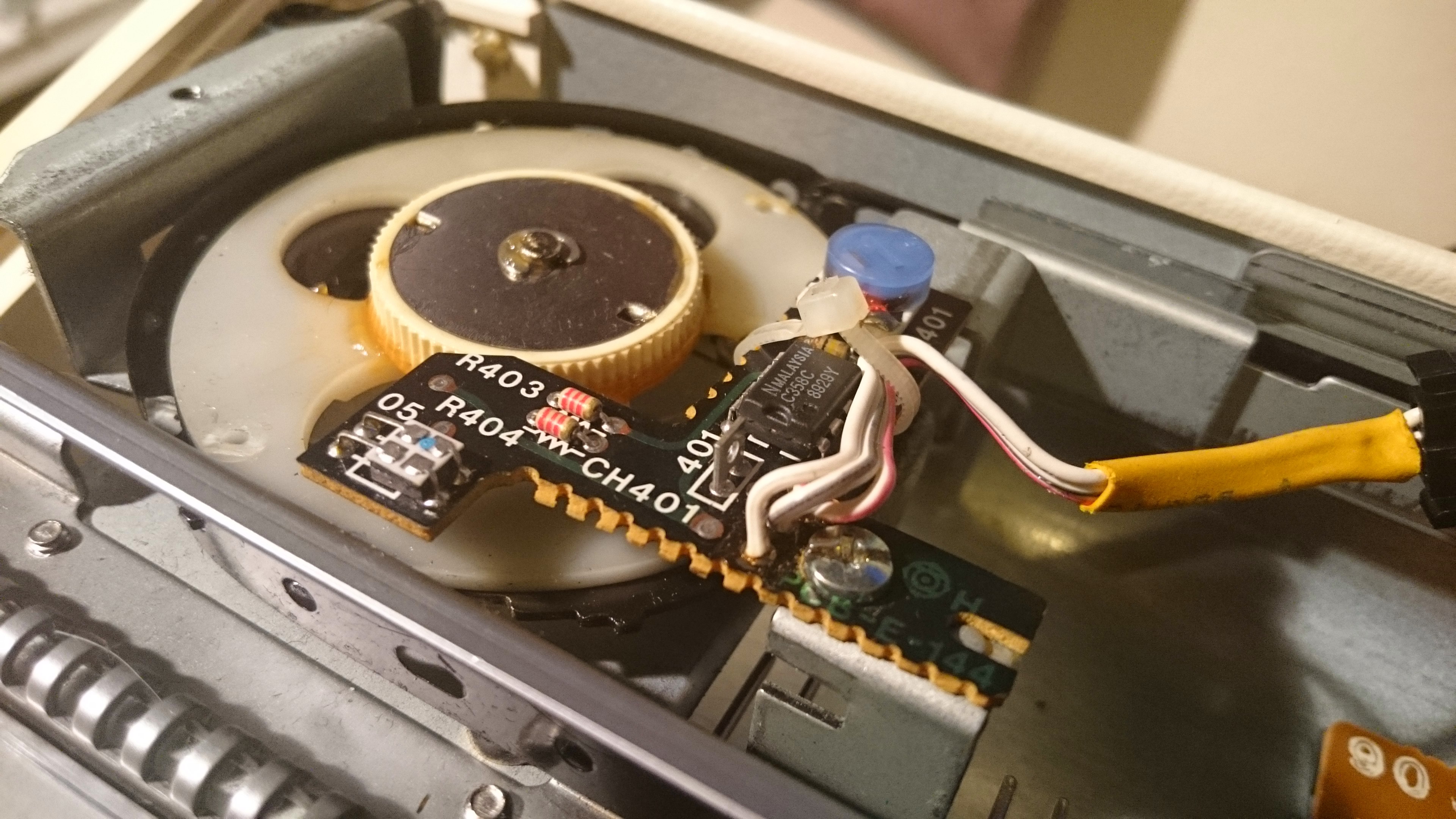
Encoder PC Board

Comprised of an optical incremental rotary encoder. The carriage connects to the timing belt which turns the rotary encoder(s). The encoder provides the signals required for calculating the amount and direction of carriage movement.
Standard Gauge Machines
Standard gauge machines have 4.5mm needle spacing and 200 needles. There are 16 solenoids and 8 needle selector plates in the needle selection mechanism.
The rotary encoders have two rings of teeth. The outer ring has 48 teeth, each representing one needle, and two opto-interrupter sensors offset by the width of half a tooth (V1 and V2).
There is an additional inner ring with 3 teeth and one opto-interrupter sensor. This provides the belt phase (BP) signal.
 Pseudo-code for calculating the carriage direction and position:
- IF V2 is HIGH AND V1 rises from LOW to HIGH THEN
- carriage is travelling to the right
- IF carriage is detected at left end sensor THEN
- position counter is 1
- determine carriage type (K, L or G)
- check belt phase to determine solenoid number
- ELSE increase position counter and solenoid number by 1
- ELSE IF V2 is HIGH AND V1 falls from HIGH to LOW THEN
- carriage is travelling to the left
- IF carriage is detected at right end sensor THEN
- position counter is 200
- determine carriage type (K, L or G)
- check belt phase to determine solenoid number
- ELSE decrease position counter and solenoid number by 1
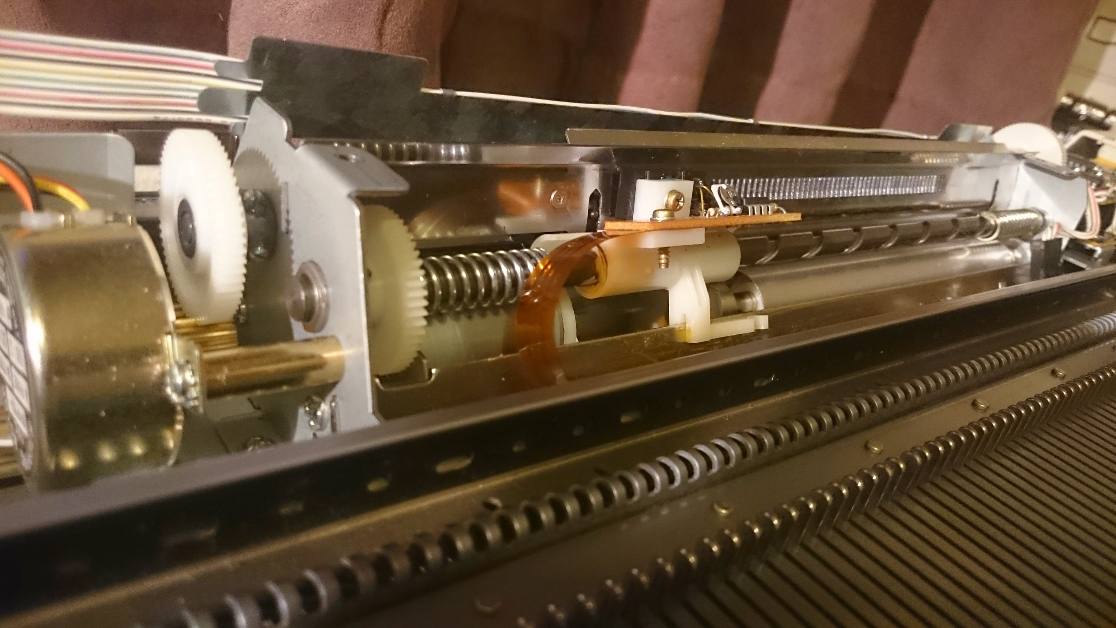
Belt Phase
The timing belt has a repeating series of circular holes interspersed with a horizontally elongated hole every 8 needles. The carriage engages with the belt at this elongated hole using connecting hook.
The needle selection mechanism operates with a 16 needle repeat. As the timing belt connector hole pitch is 8 needles there are two locations within each 16 needle repeat at which the connection could have been made and two possible solenoids to control the needle. The belt phase signal is used to decide which of the connection two locations was used and therefore which is the correct solenoid number.
The table below shows how the combination of carriage and belt phase signal translates to the solenoid number.

Bulky/Chunky gauge machines
The KH-270 chunky gauge machine has 9mm needle spacing and 112 needles. The needle selector mechanism has 12 solenoids and 6 needle selector plates.
The encoder behaves in the same way as the standard gauge machine but only has the outer ring of teeth and V1 and V2 signals as there is no need for the BP signal (I assume this means that the timing belt connector hole pitch is 12 needles). The solenoid to needle number mapping is available in the service manual.
Solenoid PC Board
Actions the solenoid selection signals provided by the main PC board by turning the solenoids on and off.
In the 950i this is buried somewhere under the card reader mechanism. I haven’t figured out how (nor been brave enough to try!) to disassemble the machine to get at the solenoid PC board yet.
Power Supply
The machines require two DC voltages to operate: 5V for the logic circuits and, depending on the model, 7.5V or 12V for the solenoids. Older models contain internal AC to DC converter and voltage regulation circuits, newer models have external adapters supplying the higher DC voltage and voltage regulators are used to generate the required 5V logic supply.
The 910 and 950i have internal AC to DC converting power supply boards which provide 5V (red cables) and 12V (orange cables).
Card reader (optional)
The 910, 950i and perhaps one or two other models came with mylar pattern card readers. The card feed row and read head stitch position are controlled by stepper and DC motors respectively, and the read head signal indicates whether the corresponding pattern square is shaded in or left blank.
The Knitic system marks the card reader rather redundant so I haven’t included information about the card reader but it is available in the KH-910 service manual.
External memory devices (optional)
An interface for the optional PPD (pattern programming devices) and floppy disk external memory systems.
I have neither system and again they are made redundant with the Knitic system being able to transfer patterns directly from the computer via the substitute electronics.
Mapping the connectors and pins
Now that I have a better understanding of the various electronics modules, what they do and why they are needed the next job is to identify the connectors removed from the old main PC board and map the individual pins to their purposes.
Do you have kh910power lead for sale thankyou for posting this I am
Hi Naheeda,
Try this power cord from Sunny Choi on eBay, the KH910 is listed as compatible.
Hope it works!
Hannah
I spent a bit of time on needle selection for Brother 950i, posted Sunday 28 June 2015. You may be interested.
Thanks Pete! Your post http://sirpetespics.blogspot.co.uk/2015/06/brother-kh-950i-knitting-machineneedle.html has helped me to better wrap my head around the mechanism. I think I need to take a close look at my machine in action to finally get there. Thanks for sharing.
Do you have a motherboard for a Brother 965i knitting machine please, or if you know where I can obtain one.
Thanks in advance
I don’t Phyl, sorry. Assuming you’re in the UK, the Guild of Machine Knitter’s website has a useful page listing repairers who might be able to help you out http://www.guild-mach-knit.org.uk/inyourarea/repairers.php. Good lucl!
thank you so much for this post.
i am having problems with the 940 power supply unit, capacitors blowing and would like to do away with it.
in my wild imaginings i’d have someone-not enough knowledge here- hack it to use the laptop + an arduino to turn it on & fire the solenoids.
Hi Neki! Great minds think alike, that was my eventual goal. Unfortunately life got in the way and progress stalled. I’m hoping to get back to this project soon but there are other people out there who have succeeded with other models of Brother machine – check out Knitic.com and ayab-knitting.com to see if they are compatible with the 940.
If I do make any progress I will be sure to post!
Hello, I was wondering if I can use a power cable from my 930 for my 950 and transformer. I inherited KH 950 , that needs a lot of cleaning , but also machine was purchased in UK and now in US.
Hi Alla
Did you find a suitable power cable?
I don’t have any experience of the 930 so I couldn’t say for sure without looking up the manual. This ebay listing http://www.ebay.co.uk/itm/271210202590 lists the same cord as compatible with both the 930 and 950 which would imply you would be fine to do so.
Sorry for my prevoius post re knitic ‘re- brain should look before I leap. I am using Linux mint, and the arduino libraries with geany etc. Also have set up eclipse for arm cross dev. Have managed to use the V1, V2 etc to get position info, and have fired off solenoid for needle select, used uno with 595s and 2803s for this on a uno dev pcb. All ok so far.
Am working on lazarus for the pc side, but I am using a raspberry pi for this running ubuntu, (ARM version). This way allows a cheap stand alone system without tying up a pc etc.
Using lazarus allows in theory write once compile to many, we will see..?
Am planning to write something similar to designaknit but only for re-brained stuff, again open-source.
Hi, Can I purchase a circuit board from somewhere for my Brother KH 530. Today I switched it on and after a few seconds there was a ‘pop’ and smoke coming from the r/h side.
Hi Beverly
Have you managed to get your machine fixed?
You can’t buy new boards as far as I’m aware, as they are no longer manufactured. For a direct replacement your best bet would be to approach a knitting machine service engineer and see if they have any.
However from the symptoms you describe it sounds like it’s your power capacitor that blew up, rather than your main circuit board. That’s a common problem and the fix is well documented – see http://www.machine-knitting.net/machineknittingnet/how-to-fix-a-brother-kh930-knitting-machine-with-wont-turn-on-or-no-power-fault/ or http://too-many-hobbies.blogspot.co.uk/2012/09/fixing-brother-950i-electronic-knitting.html. This ebay seller even provides a replacement parts kit http://www.ebay.co.uk/itm/Brother-KH-Series-Knitting-Machine-2-x-Capacitor-Quick-Blow-Fuse-Repair-Kit-/121155652964
How do I access the needle bed of the brother KH 950i knitting machine? I recently got the machine out of the attic from a 15 year hibernation and stripped it down to clean only to find needle G52 will not go back into postition A (parked at back). There is, presumably, something in there. How do I get to the back of the needle bed in the machine?
That’s something I’d love to figure out myself! I never got as far as removing the needle bed, although I need to in order to get access to the solenoid pcb. Did you find the answer? Please let me know if you did!
Hello I bought Kh910 and I have problems with the reader card 881 error 1 or 2 or 3, tension of CH501 is good. I can program but cf do not work and mark error. I verified the tensions and at the level of S5 on pcb right (E_144) i have 0V in blue Electric cord inside 5V on p5 it is normal?
Thank you for your help.
Hi Dana,
It’s been a while since I’ve looked at my knitting machine and I don’t have a 910 so unfortunately I don’t know the answer. Have you managed to get your errors fixed?
Thank you, but I noticed that according to the position of the carriage I had different errors thus I had thought of hacker the machine but am not certain that it
will work.