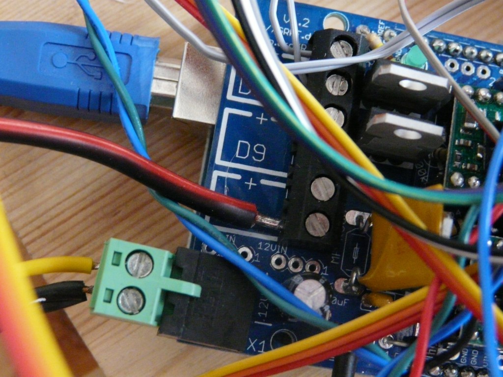
Having assembled the RAMPS kit and received a new heated bed to replace the broken one, it was for Mendel’s first major overhaul – replacing Techzone Gen3 electronics, and adding a heated bed.
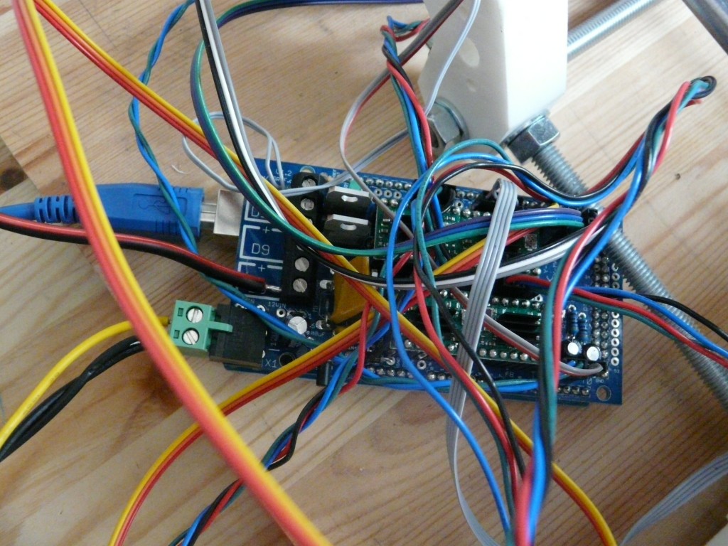
Our original set up had been Techzone Gen3 electronics that we ordered from America, as seen in previous posts. Moving over the RAMPS wasn’t too painful, as I just redid all the wiring and kept the old electronics as a complete set. The wiring is a bit of a mess at the moment though, and I need to sort out a mounting solution for the RAMPS board.
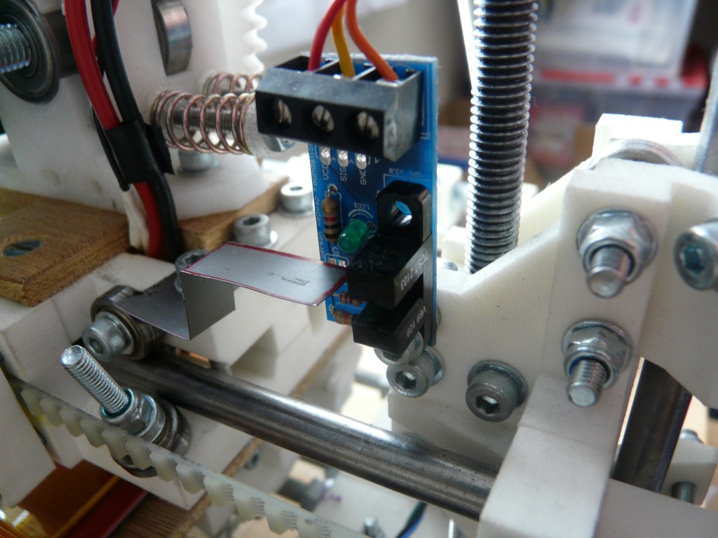
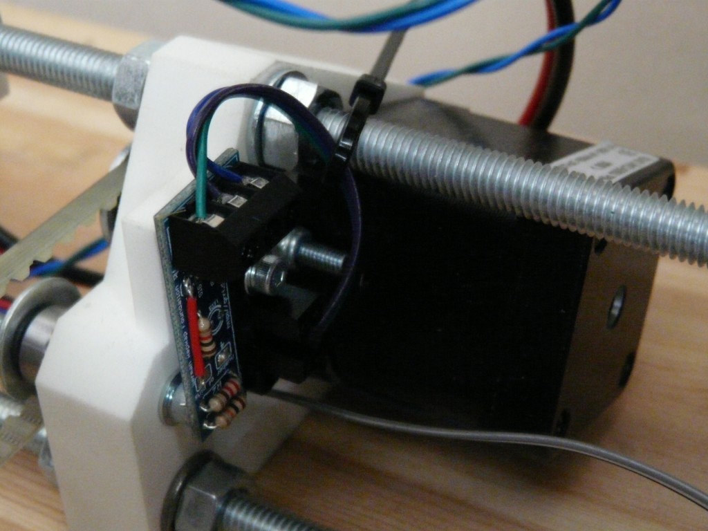
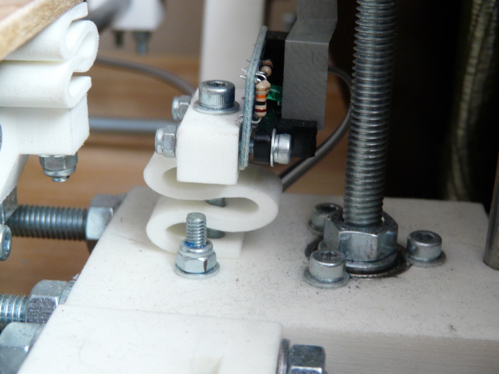
 One of the biggest challenges always seems to be where to mount the endstops, and as the RAMPS ones are bigger than the Techzone Gen3 I was worried that it would be a big task. Luckily not though! Here is how I’ve set them up:
X Axis:
Z Axis:
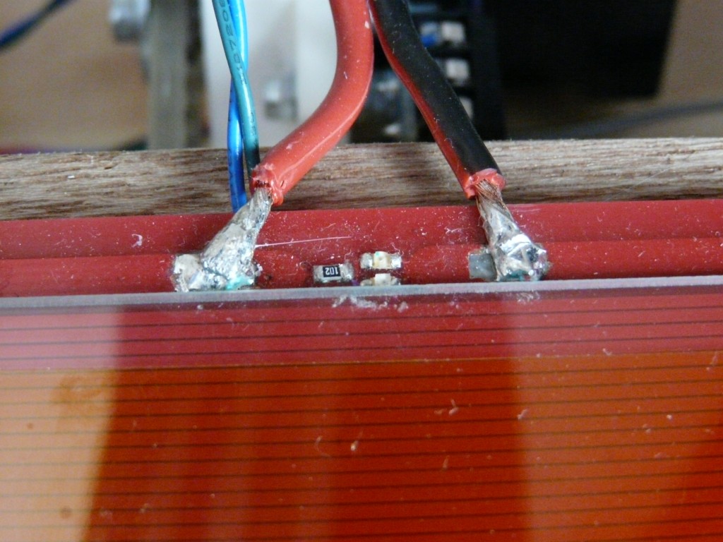
After learning my lesson with the previous PCB heated bed, I decided against using the hot plate to solder the LEDs and resistor and instead used a flux pen and soldering iron. It was easier than I expected, but I ended up with a little bit too much solder. The real problem came with the heater wires. I soldered them to the pads and mounted the bed according to Prusa’s instructions, but the movement of the bed ripped the pads off the PCB! Luckily I could scratch some of the solder resist off to make bigger pads and spread the wire a little to increase the contact area and solder them back on.
I obviously need to have a bit of a dust!
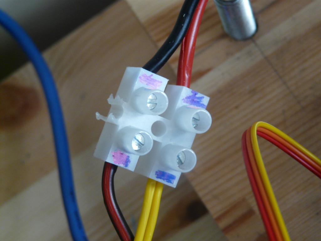
Here is how the heated bed wiring is set up. The wires from the heated bed go to a chocolate block connector. One wire is connected to the 12V of the PC power supply, then other to the ground of the RAMPS heated bed connector.
We’re using a 200mm square sheet of 2mm float glass that we got from a local glaziers, covered in Kapton tape as the print area. The PLA sticks really well.


