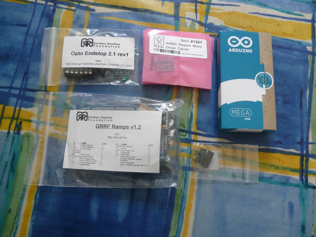
Our RAMPS 1.2 Electronics kit arrived from German RepRap Foundation the other day so I got cracking! Unfortunately I has having one of those days and my German and Google Translate weren’t too great, resulting in several LEDs with the wrong orientation and one in completely the wrong place! Thankfully everything still works (except the LEDs).
The kit was nicely packaged and labelled. I was surprised at the Arduino Mega coming fully assembled, but that was great – less work for me!
The assembly instructions for the Opto Endstops are on the GRRF Wiki and are in German.
The assembly is pretty straight forward, all through-hole components with two pads to bridge depending on whether the optical sensor has 4 or 5 legs. However the orientation of LEDs always trips me up and in this instance the Google Translated version of the instructions was not my friend! “When the LED must show the mass-leg to the light barrier.” made not a whole lot of sense, but seemed to be saying the long i.e. positive leg should be next to the optical sensor. Couldn’t be more wrong! Studying the traces on the PCB in the photo on the wiki (also shown below), it is possible to see that the trace connected to the VCC pad connects to the LED pad furthest from the optical sensor.

Shame I didn’t find this out until I had soldered all the LEDs into place the wrong way around! I tried to remove one LED but ended up removing the pad with it, and so accepted defeat – LEDs that don’t work. The lesson from this mistake – when it doubt, figure it out from the schematic and don’t rely on some dodgy Google Translation!
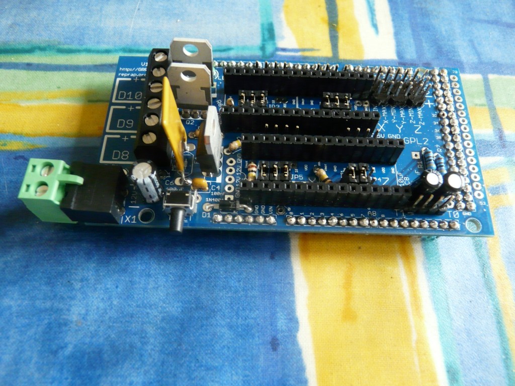
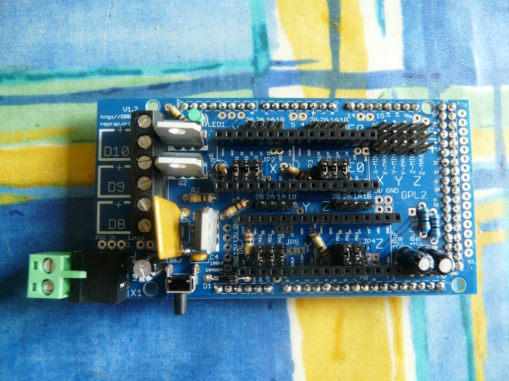
The RAMPS 1.2 main board was also fairly simple, and made easier by the instructions being on the RepRap wiki in English, which comprise a recommended order of components. At first its seems a little bare but in combination with the silkscreen and photos it is clear what goes where. That said, I still managed to made the harebrained mistake of soldering the LED where one of the electrolytic capacitors was meant to be. Luckily this situation was salvaged without too much fuss.
And here is the finished result:
The kit was definitely a great deal, with the Opto Endstops effectively included for free compared to the price of buying the RAMPS 1.2 kit and Pololus separately. Easy to assemble too, despite the silly mistakes that on any other day I probably wouldn’t have made. The only negative point is that 1.3 came out not too long ago and is touted as having much better heated bed support, along with a slot for an extra extruder although that is probably getting a little ahead of ourselves!
Next task – uploading the firmware.


